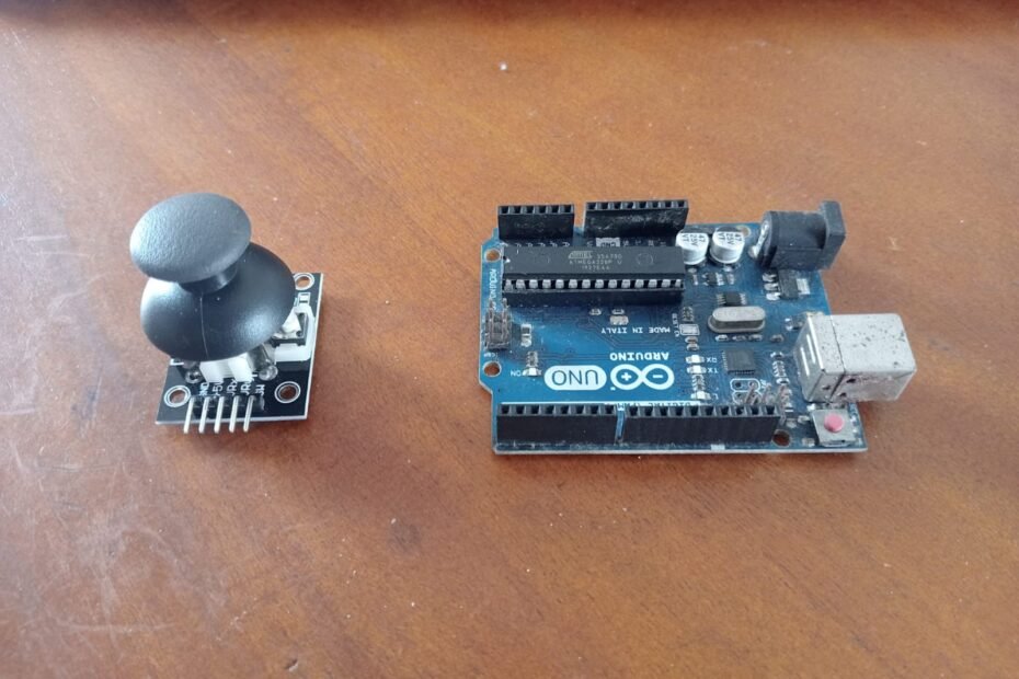
1. Brief Description of Joystick Sensor (KY-023)
The KY-023 joystick sensor module is a versatile component that can detect directional movement along the X and Y axes, as well as a button press when the joystick is pushed down. It’s commonly used in gaming, robotics, and various control applications. For more help and to ask questions, visit our forum here.
2. Parts Needed
- Arduino Uno
- KY-023 Joystick Sensor Module
- Breadboard
- Jumper wires
3. Circuit Connection
Connect the joystick sensor to the Arduino as follows:
- VCC to 5V on Arduino
- GND to GND on Arduino
- VRx to Analog pin A0 on Arduino
- VRy to Analog pin A1 on Arduino
- SW to Digital pin 2 on Arduino
Here is a schematic for clarity:
Joystick Arduino
——- ——-
VCC -> 5V
GND -> GND
VRx -> A0
VRy -> A1
SW -> D2
4. Code
Here’s a sample code to read the values from the joystick and print them to the Serial Monitor:
// Define pins
const int VRx = A0;
const int VRy = A1;
const int SW = 2;

void setup() {
  // Initialize the serial communication
  Serial.begin(9600);

  // Set the button pin as input
  pinMode(SW, INPUT_PULLUP);
}

void loop() {
  // Read the joystick axes
  int xPosition = analogRead(VRx);
  int yPosition = analogRead(VRy);

  // Read the button state
  int buttonState = digitalRead(SW);

  // Print the values to the Serial Monitor
  Serial.print("X: ");
  Serial.print(xPosition);
  Serial.print(" | Y: ");
  Serial.print(yPosition);
  Serial.print(" | Button: ");
  Serial.println(buttonState);

  // Small delay to stabilize readings
  delay(200);
}
5. Testing and Results
- Upload the code to your Arduino board.
- Open the Serial Monitor in the Arduino IDE (set the baud rate to 9600).
- Move the joystick around and observe the X and Y values changing.
- Press the joystick button and see the button state change from 1 to 0.
You should see output similar to:
X: 512 | Y: 512 | Button: 1
X: 600 | Y: 300 | Button: 1
X: 400 | Y: 700 | Button: 0
6. Troubleshooting
- No output in Serial Monitor: Ensure the correct COM port and board are selected.
- Incorrect or no readings: Check the wiring, especially the connections to the analog pins.
- Button always reads 1: Verify the pinMode is set to INPUT_PULLUP and check the connection to the SW pin.
7. Example Project Ideas
- Joystick Controlled Robot: Use the joystick to control the movement of a robot.
- Game Controller: Create a simple game controller for a PC game.
- Panning Camera: Control the angle of a camera using servos and the joystick for smooth panning.