Part 1: Introduction
Welcome to this step-by-step guide on building your very own Arduino Traffic Light Controller. This project is perfect for those who are just starting their journey into the world of Arduino and electronics.
The Arduino Traffic Light Controller is a simple yet exciting project that will introduce you to the basics of Arduino programming and electronics. By the end of this guide, you will have a working traffic light system that you can show off to your friends and family!
If you are stuck in any of the steps below and can’t find what to do please feel free to ask from us Here.
Objective of the Project
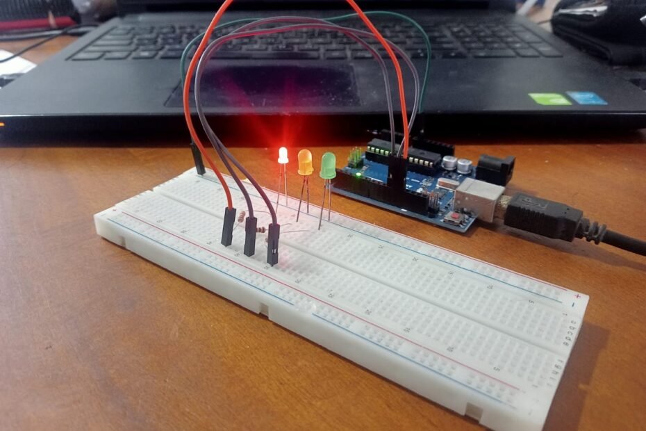
The objective of this project is to create a traffic light controller using an Arduino. The traffic light will cycle through red, yellow, and green lights, just like a real traffic light. This project will help you understand how to control LEDs using an Arduino and how to write simple Arduino programs.
In the next part of this guide, we will discuss the materials needed for this project and how to set up your Arduino.
If you are a beginner and haven’t purchased the components yet, we recommend buying this Arduino starter kit. It will save you time and money and also will open the door for many other projects.
Part 2: Materials Needed
Before we start building our Arduino Traffic Light Controller, let’s gather all the necessary components. Here’s a list of what you’ll need:
- Arduino Uno Board: This is the brain of our project. The Arduino Uno is a microcontroller board based on the ATmega328P.
- LEDs: We will need three LEDs of different colors – red, yellow, and green. These will serve as our traffic lights.
- Resistors: We will need three 220-ohm resistors. These are used to limit the current to the LEDs and prevent them from burning out.
- Breadboard: A breadboard is used for making an experimental model of an electric circuit.
- Jumper Wires: These are used to connect the components on the breadboard to the Arduino Uno board.
- USB Cable: This is used to connect the Arduino Uno to your computer for programming.
Once you have all your materials ready, we can move on to setting up your Arduino.
In the next part of this guide, we will walk you through the process of setting up your Arduino and installing the Arduino IDE. Stay tuned!
Part 3: Setting Up Your Arduino
Now that we have all our materials ready, let’s set up our Arduino.
Installing the Arduino IDE
The Arduino IDE (Integrated Development Environment) is a software that allows us to write and upload code to the Arduino board. Here’s how to install it:
- Visit the official Arduino website and download the latest version of the Arduino IDE that is compatible with your operating system.
- Once the download is complete, open the installer and follow the prompts to install the Arduino IDE on your computer.
- After the installation is complete, open the Arduino IDE to ensure it is installed correctly.
Connecting the Arduino Uno to Your Computer
Now, let’s connect the Arduino Uno to your computer:
- Take your USB cable and connect one end to the Arduino Uno and the other end to a USB port on your computer.
- Once connected, your computer should recognize the Arduino Uno as a new device and install the necessary drivers.
Congratulations! You have successfully set up your Arduino. In the next part of this guide, we will start building the circuit for our Arduino Traffic Light Controller.
Stay tuned for the next part where we will dive into the exciting world of electronics and start building our traffic light system!
Part 4: Building the Circuit
Now that we have our Arduino set up and ready, let’s start building our traffic light circuit.
Understanding the Circuit Diagram
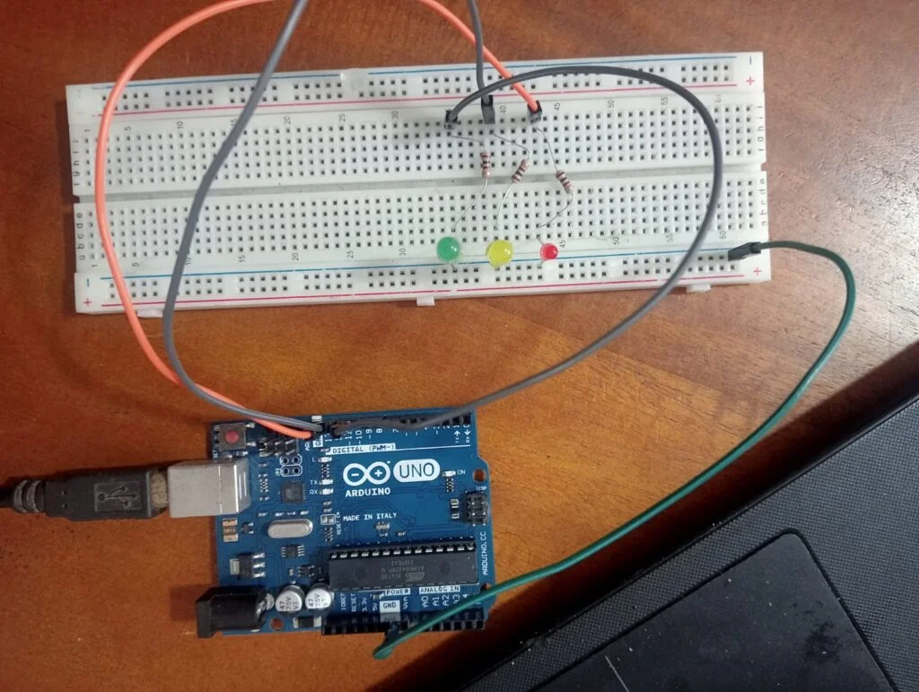
Before we start building, it’s important to understand the circuit diagram. The circuit diagram shows how the components are connected to the Arduino. In our case, we will connect the LEDs to the digital pins of the Arduino through the resistors.
Building the Circuit
Follow these steps to build your circuit:
- Place the LEDs on the Breadboard: Place the red, yellow, and green LEDs on the breadboard. Make sure the longer leg (anode) of each LED is in a separate row from the shorter leg (cathode).
- Connect the Resistors: Connect a 220-ohm resistor to the anode of each LED. This will limit the current of the LEDs and prevent them from burning out.
- Connect the LEDs to the Arduino: Use jumper wires to connect the other end of each resistor to a digital pin on the Arduino. Connect the red LED to pin 13, the yellow LED to pin 12, and the green LED to pin 11.
- Connect the Ground: Use a jumper wire to connect the cathodes of the LEDs (the shorter leg) to the ground (GND) pin on the Arduino.

Congratulations! You have successfully built the circuit for your Arduino Traffic Light Controller.
In the next part of this guide, we will dive into the exciting world of Arduino programming and write the code for our traffic light system.
Part 5: Programming the Arduino
Now that our circuit is ready, it’s time to program our Arduino to control the traffic lights.
Understanding the Code
The code for our Arduino Traffic Light Controller is quite simple. We will use the digitalWrite() function to turn each LED on and off, and the delay() function to control the timing of the lights.
Writing the Code
Here’s the step-by-step guide on how to write the code:
- Open the Arduino IDE: Start by opening the Arduino IDE on your computer.
- Create a New Sketch: Click on
File > Newto create a new sketch. - Write the Code: Copy the following code into your new sketch:
// Define the LED pins
#define RED_LED 13
#define YELLOW_LED 12
#define GREEN_LED 11

void setup() {
  // Set the LED pins as output
  pinMode(RED_LED, OUTPUT);
  pinMode(YELLOW_LED, OUTPUT);
  pinMode(GREEN_LED, OUTPUT);
}

void loop() {
  // Red light
  digitalWrite(RED_LED, HIGH);
  delay(5000); // Wait for 5 seconds
  digitalWrite(RED_LED, LOW);

  // Yellow light
  digitalWrite(YELLOW_LED, HIGH);
  delay(2000); // Wait for 2 seconds
  digitalWrite(YELLOW_LED, LOW);

  // Green light
  digitalWrite(GREEN_LED, HIGH);
  delay(5000); // Wait for 5 seconds
  digitalWrite(GREEN_LED, LOW);
}
- Upload the Code: Connect your Arduino to your computer using the USB cable. Then, click on
Sketch > Uploadit to upload the code to your Arduino.
Congratulations! You have successfully programmed your Arduino Traffic Light Controller.
In the next part of this guide, we will test our traffic light system and troubleshoot any issues that might arise. Stay tuned!
Part 6: Testing and Troubleshooting
Now that we have built our circuit and programmed our Arduino, it’s time to test our Arduino Traffic Light Controller.
Testing the System
- Power Up: Connect your Arduino to your computer using the USB cable. The LEDs should start cycling through red, yellow, and green lights.
- Observe the Lights: The red light should be on for 5 seconds, followed by the yellow light for 2 seconds, and then the green light for 5 seconds. This cycle should repeat indefinitely.
Troubleshooting
If your traffic light system is not working as expected, here are some common issues and how to fix them:
- LEDs Not Lighting Up: Check your connections. Make sure the anode (longer leg) of each LED is connected to the resistor and the cathode (shorter leg) is connected to the ground (GND).
- LEDs Lighting Up in the Wrong Order: Check your code. Make sure you have connected the LEDs to the correct pins on the Arduino and that your code matches these connections.
- LEDs Not Cycling Correctly: Check your code. Make sure your delay times are correct and that your
digitalWrite()functions are turning the LEDs on and off in the correct order.
Remember, troubleshooting is a normal part of the learning process. Don’t get discouraged if things don’t work perfectly the first time. Keep trying, and don’t hesitate to ask for help if you need it.
Congratulations! You have successfully built and programmed your very own Arduino Traffic Light Controller. We hope this guide has been helpful and has sparked your interest in Arduino and electronics. Happy tinkering!
Part 7: Conclusion
Congratulations on successfully building and programming your very own Arduino Traffic Light Controller! This project not only allowed you to learn the basics of Arduino programming and electronics but also gave you a hands-on experience of building a working model of a traffic light system.
Remember, the world of Arduino and electronics is vast and there’s always something new to learn. Don’t stop here. Continue exploring, building, and creating. The skills you’ve learned from this project can be applied to more complex projects in the future.
We hope this guide has been helpful and has sparked your interest in Arduino and electronics. Keep experimenting, keep learning, and most importantly, have fun!
That concludes our step-by-step guide on building an Arduino Traffic Light Controller. We hope you found it informative and engaging. If you have any questions or need further clarification on any part of this guide, feel free to ask. Happy tinkering!
